If you haven’t read parts one and two of the series, I’d suggest reading them for some background. Long story short: I won a raffle and got a box of assorted hardware from Hackster.io in a contest from a Microsoft/AVnet collaboration. The deal was that over 20,000 people (including myself) received an AVnet Azure Sphere MT3620 development board to try to make something interesting with.

And, well, sadly, my C/C++ programming skills in the embedded space are almost nonexistent (unless you count Arduino as C). I kept the board online for the 15 days to win the Raspberry Pi, and won the raffle though, so I have definitely got the better end of this deal.
After getting my hardware though, I noticed something quite interesting: This board has a Grove connector and two mikroBus slots. Previously, I didn’t have any devices which used Grove or mikroBus to test with. But now, with a Relay mikroBus Click Board and a whole box of Grove sensors, I wondered if there was, perhaps, a better way to program the MT3620.
It turned out, with some digging, that there was a better way to program it for my purposes. A programmer named Georgi Angelov (aka @Wiz-IO) released a mostly-complete port of PlatformIO to the MT3620. PlatformIO’s basic goal is to add support for multiple ecosystems (Arduino, ESP, Linux) to multiple boards (Arduino, Raspberry Pi, Adafruit Feather). There are obvious incompatibilities (your Arduino isn’t going to support the Linux ecosystem), but it is still a neat attempt at cross-platform embedded programming. By porting the AVnet board with the MT3620 to PlatformIO, it could be possible to write Arduino programs and run them on the dev board.
Of course, I was hooked and began digging through his code. It’s sadly not a complete PlatformIO port, and it hasn’t been updated in a while. Furthermore, it appears (please pardon me if I am mistaken) that English is a second language to Angelov, and so some of the documentation is difficult to understand and is not as clear as it could be. He also has no screenshots of the install process. That didn’t stop me from doing what I could with his code.
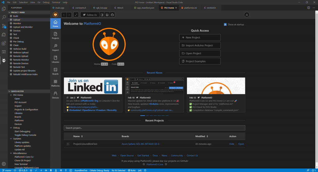
I started by installing PlatformIO into Visual Studio Code. It looks quite interesting, no matter what board you are using:
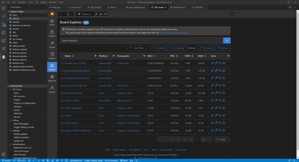
The Avnet MT3620 development board is sadly not one of the officially supported 700+ boards yet. That’s where Angelov’s port comes in. I had to install it manually into PlatformIO, but that was shockingly easy. PlatformIO just lets you paste in a GitHub URL, and it will automatically fetch the custom board information. (I wish all development tools could do stuff like this.) If you are following along, be aware that the original port requires some lines of code to be changed to work on the newer SDKs.
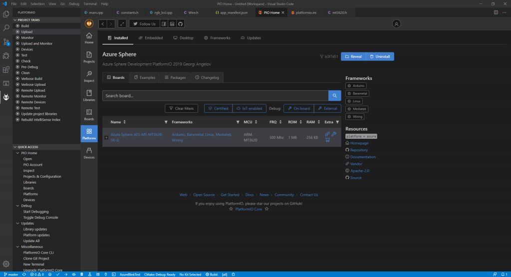
Once installed, you should see something like this:
If you click on the examples tab, you should see this:
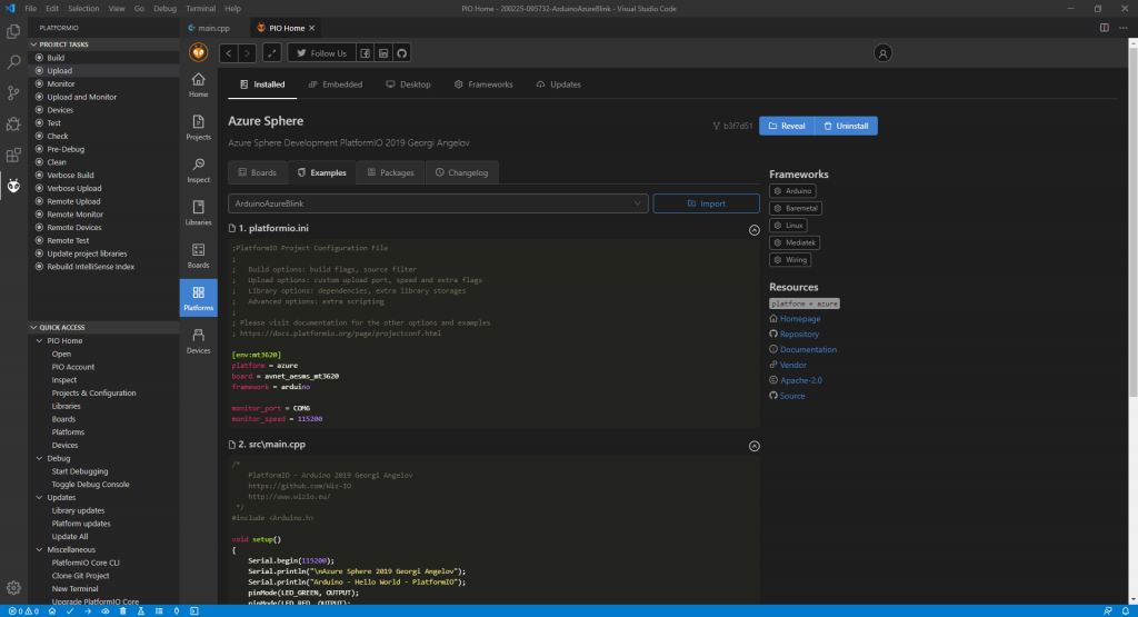
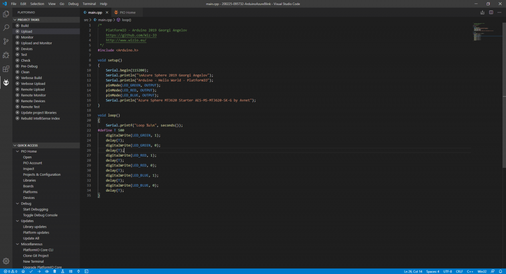
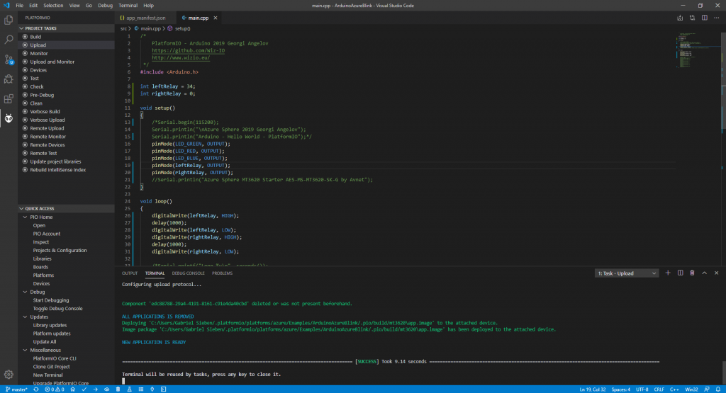
Click “Import,” and PlatformIO will soon give you a path to a folder containing the code. Open that folder within Visual Studio Code, and open the src/main.cpp file. Admire it’s Arduino-like syntax:
However, we aren’t out of the woods yet. The SDK platform installs for Azure Sphere has significant issues with the AVnet development kit. This can be fixed according to the Install Notes (which are actually for 19.10 SDKs and higher, not just that particular SDK) with the following instructions:
- Close Visual Studio Code. It might overwrite files we’ve changed.
- Open the folder
C:\Program Files (x86)\Microsoft Azure Sphere SDK\Toolsin a File Explorer window. - Open the folder
C:\Users\YourUserName\.platformio\packages\tool-azure\azspherein another File Explorer window. - Select all items in the first folder with
CTRL+A, and then drag the items into the PlatformIO folder, while holding down theCTRLkey to Copy instead of Move. If File Explorer asks you what to do with duplicates, choose Replace. - Close both windows.
The next step is to open the folder C:\Users\YourUsername\.platformio\platforms\azure\builder\frameworks in a File Explorer window. Open the file common.py and look for this block of code:
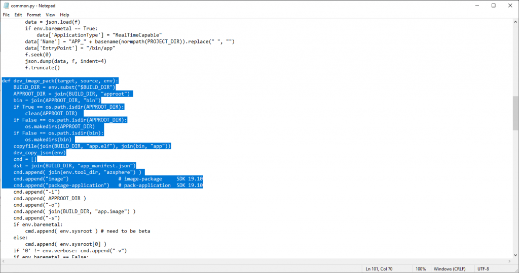
See the last lines of the highlighted area? Replace image with image-package and package-application with pack-application as the comments indicate. It should now look like this:
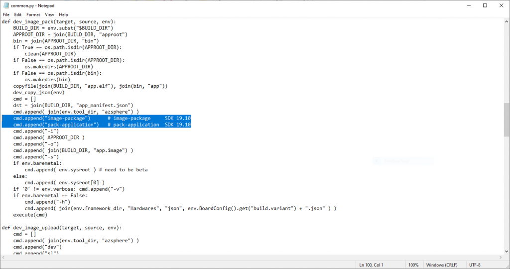
Save and close.
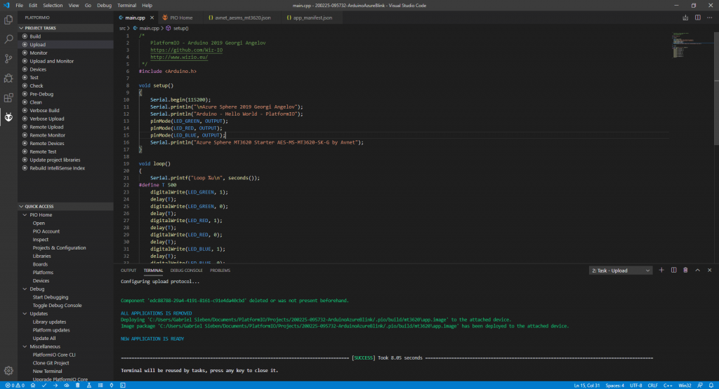
Open up Visual Studio Code again, click the PlatformIO Sidebar rail, and chose “Upload.” If all goes well, it should run the Blink sketch on your MT3620! Please be aware that even though Angelov lists Serial as supported (and has it working on video), I have not managed to get Serial communications to work on any COM port in Windows.
There are some immediate differences with this Blink sketch and the regular Arduino Blink sketch though. The first is the #include <Arduino.h> at the top of the file. Because Arduino is technically based on C and is a (very large) C library, we are importing that into our code. The second thing you may notice is that the code already knows what GREEN_LED, BLUE_LED, and RED_LED are. These are defined in the board variant file, which includes definitions for board-specific variables:
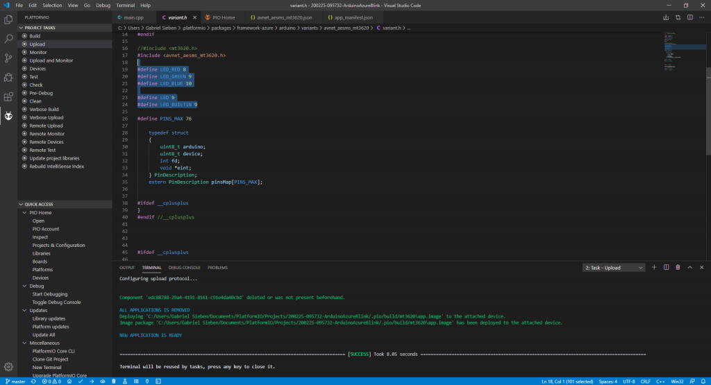
The third, and last thing to notice is that I am setting the LEDs that I want to turn on to LOW, and the LEDs I want to turn off to HIGH. What gives? Well, it’s a quirk with the onboard LEDs on the AVnet board itself. This doesn’t happen with external LEDs. For the board’s onboard LEDs, 0/LOW is on and 1/HIGH is off. This quirkiness is not unique to the Arduino on MT3620 components. This happens even in the Azure Sphere example sketch, which I’ve customized slightly to make the point:
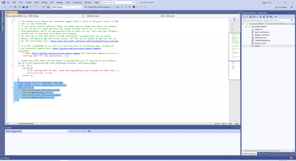
Looking at my example derived from an official example, it would appear that this would turn the LED off for two seconds and on for one second in a loop. Nope. Because LOW is on and HIGH is off for those onboard LEDs, this actually turns the LED off for one second and on for two seconds. So, it’s not Arduino-specific, it’s just the onboard LEDs on the AVnet board in general. Weird. If anyone has any ideas why this is, let me know.
Back to the board though. Now that I had the RGB LEDs blinking on the board, I looked at my Relay Click board. How hard could it be to get running on the MT3620?

This relay click board will snap perfectly into one of the two sockets on the MT3620. I opened up the relay’s product page and ran to the pinout diagram.
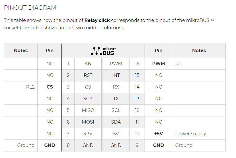
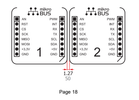
So, for the left side relay, I need to turn Pin 3 to high to activate the relay. For the right side relay, I need to activate Pin 16 to trigger the relay. But hold on: This is on the Relay board itself. The pins have completely different from the Arduino’s perspective: The pins certainly aren’t the same if you plug the board into, say, Socket #2 instead of Socket #1, or vice versa. How do you find the correct pins?
After some searching, I found the official datasheet for the AVnet MT3620 development board. And it’s right in there:
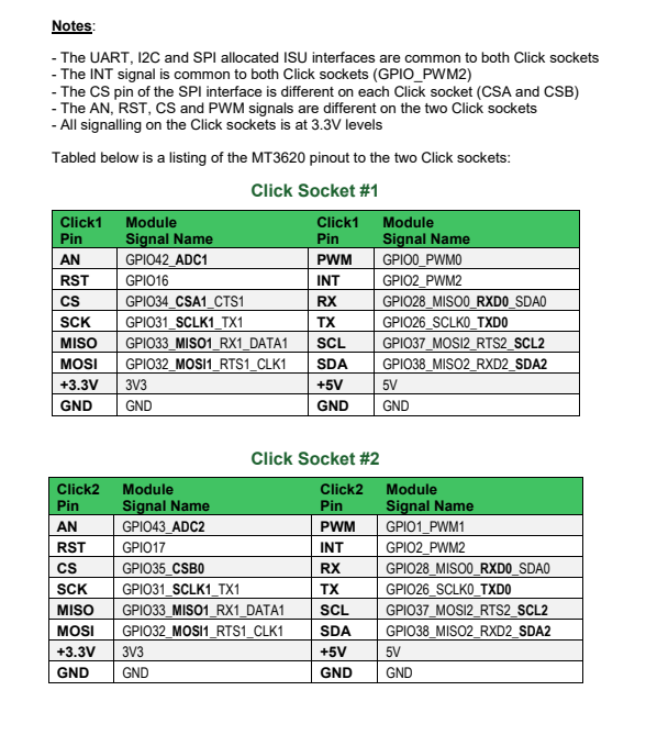
Looking back at the Click board, I need to activate Pin 3 / CS to activate the left side relay, and Pin 16 / PWM to activate the right side relay. The module name for the left side pin is GPIO34_CSA1_CTS1, and the module name for the right side pin I need is GPIO0_PWM0.
But, alas, I’m not done yet. Every Azure Sphere program has a app manifest, and this app manifest lists every capability your program (or in this case, sketch) has. It’s kind of like a permissions system for Android or iOS. It looks like this in your folder:
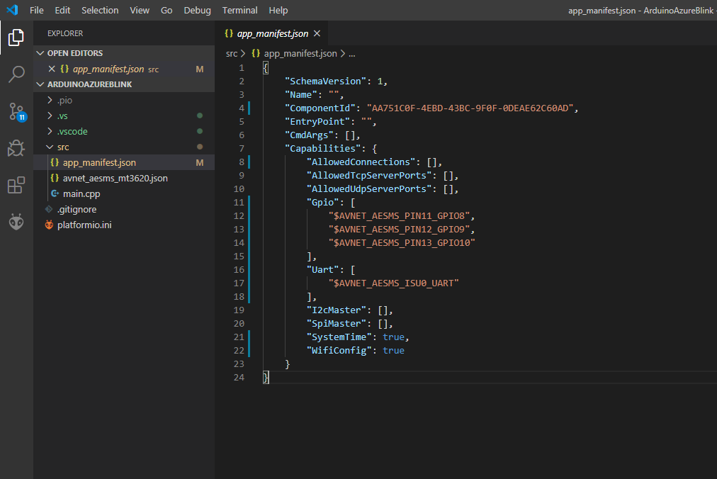
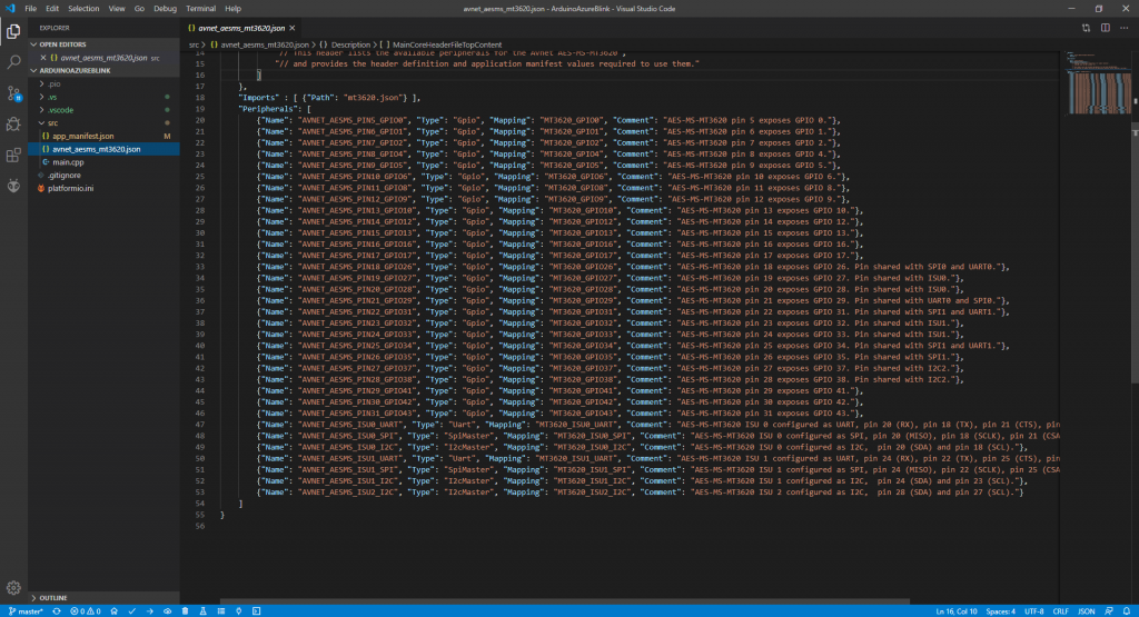
Right now, I have GPIO pins 8, 9, and 10 allowed, which are the three onboard LEDs. Using the module names, I know that I need to allow GPIO pins 34 and 0. You may notice the odd “PINX-GPIOY” format. I have no idea what the “PINX” value is for, and it’s not consistently changing with the GPIO value either. We want to match the GPIO value. This is where that avnet_aesms_mt3620.json file (also available here) comes into play. It includes a list of all possible permissions for the board.
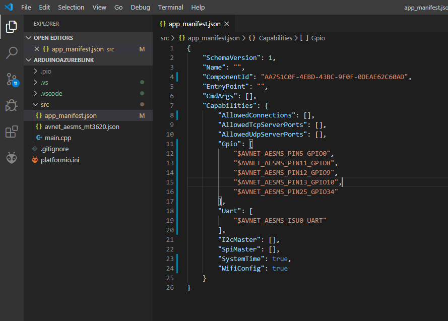
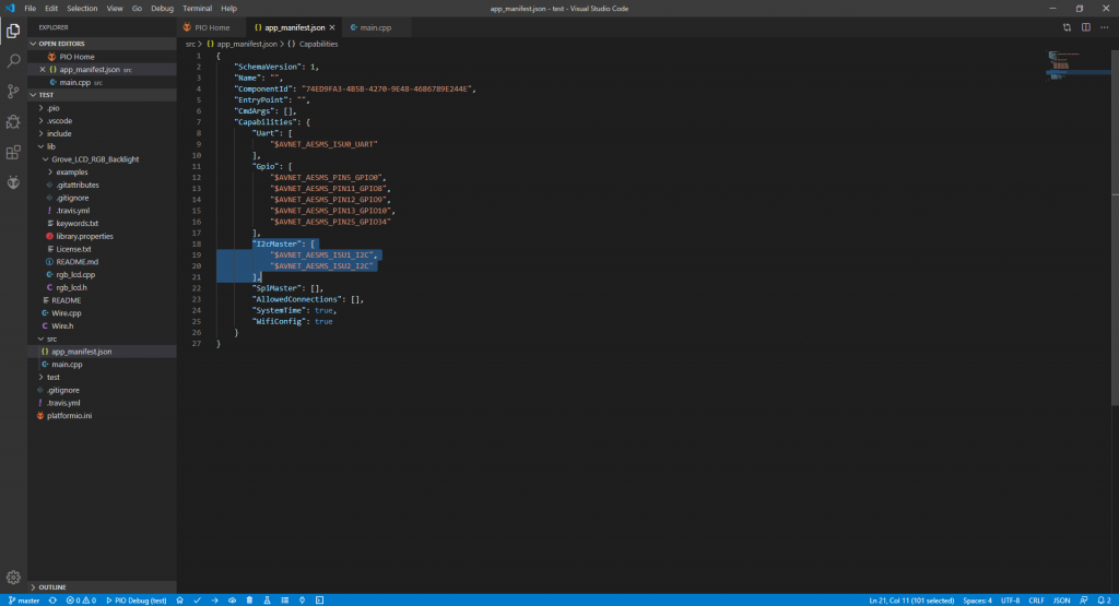
For pin 34, I need to add AVNET_AESMS_PIN25_GPIO34 to my app manifest. For Pin 0, I need to add AVNET_AESMS_PIN5_GPIO0 to the manifest. My final manifest looks like this:
With all of that permissions work doing, it’s time to try controlling the Relay click board from the MT3620! Open up main.cpp and let’s add a bit of code to control our relays:
Upload, and with that, I’ve built a relay metronome!
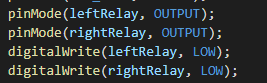
Awesome as this is, there is one little bug: When a new pin is initialized with pinMode(), that pin is automatically set to HIGH, resulting in both relays being turned on until the code turns one off. I’m not sure quite why this is, but it means that the relay momentarily turns both relays on. I just follow up my pinMode() calls with a simple digitalWrite() call to take care of that.
So, what do I have so far? An MT3620 with the ability to package Arduino sketches to run on it, and a working Relay click shield. What about a Grove module? There’s a Grove connector just sitting there. And not just any Grove module with a single-wire signal: A Grove module which uses I2C.
I immediately reached for the best I2C Module in the Grove box: The RGB Backlit 16×2 LCD display. For that module, there is an Arduino library, which I extracted into a convenient libs folder in my sketch.
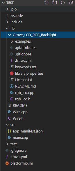
After this, I had one major problem: the build process couldn’t find Wire.h, which is a pretty common library. Odd. Just as an experiment, I tried downloading a new copy of Wire.h online and putting it in the libs, but it didn’t work. After some researching, I found that PlatformIO comes with a working Wire.h and Wire.cpp in the C:\Users\YOURUSERNAME\.platformio\packages\framework-azure\arduino\libraries\Wire\src folder. It is supposed to be included in the build path, but PlatformIO shows that it is in the build path already, so I am not sure what’s going on. I copied the wire files from there into the root directory of lib and my build succeeded!
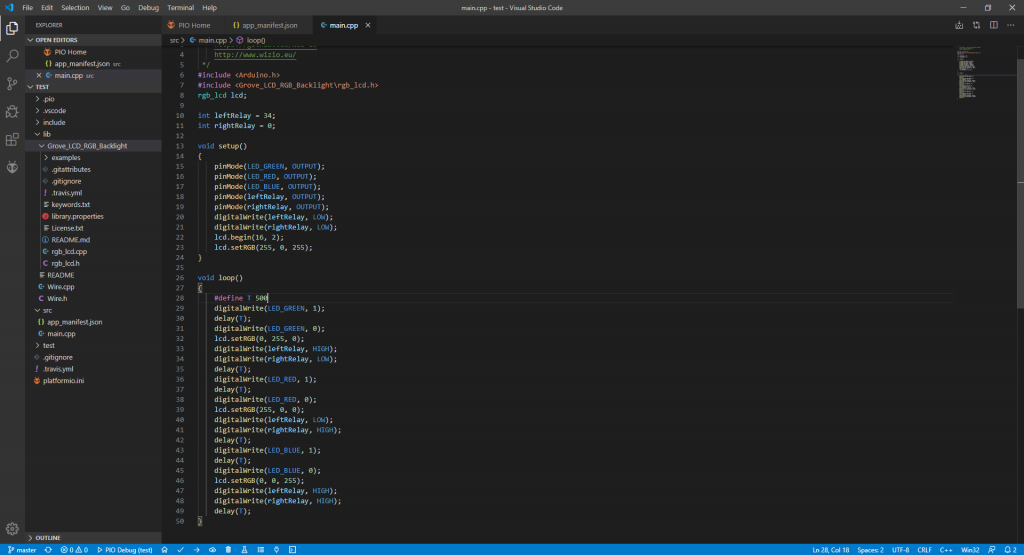
I then got excited and immediately wrote some code to do an RGB blinking sequence on the LED, with the RGB onboard light and relay working together.
I uploaded it… and it didn’t work! After some thinking, I realized I forgot to add I2C permission to my app manifest.
With that out of the way, I clicked “Upload” and… well, the RGB Backlight was flashing, showing that I2C sensors were completely workable with Grove! Alas, I made one major oversight: The LCD module needs 5V, whereas the MT3620 provides only 3.3V (as most Grove sensors need only 3.3V, the LCD being the exception to the rule). As a result, even though the backlight works, the LCD could not display any text when I tried due to not enough power. I had a similar issue on the Edison board, so this isn’t a communications problem.
Ladies and Gentlemen, there you have it. An MT3620 development board running an Arduino sketch on a Linux-based OS from Microsoft, controlling a mikroElektronica Relay Click board and an I2C Grove LCD Display. Of course, the possibilities could go on a long way from here. There are definitely disadvantages to programming your MT3620 this way: It’s unfinished, some things like Serial don’t work, and you can’t accept or send many important system calls (i.e. your app can’t receive warnings of an incoming update or reboot, for example). Still, being able to program the MT3620 like an Arduino makes prototyping much easier than writing C++, and I can’t wait to see what I will use the MT3620 for in the future.
You’ve gotten astonishing stuff right here.